


 Member
In process of adding a ballast system, going the reversible pump route. Trying to figure out how to wire this, the only hangup I haven't figured out is how to power each switch. I was planning on pulling power from the open battery spade, to a 14 ga power block, from the block to each switch, fused with a 20 amp inline fuse. The only thing I don't know is, can that little circuit board I am pulling power from handle this much current draw? Each pump is rated at 20A, not sure if I have all 3 pumps running, I don't know if that board can handle this? Has anyone ever measured how much current is being drawn when all 3 pumps are running? Thoughts?
Also, if anyone has a schematic of how to wire each switch, I think I have it, but just want to make sure I have the correct one. All of my parts from Wakemakers are coming Friday, I think it may come with a wiring diagram, not sure.
ballast wiring.jpg

2002 Outback LSV
Super Moderator

I personally would not pull all the power off that board.
I would pull a line firectly from the fuse block if it has a hot terminal or right from the main battery, threw a block that you can seperate each pump threw. Im not exactly sure how much power those pumps are pulling but i know its over 15 amps and less then 20 each pump. I have also been told its best to have the engine running in the boat when poweing all threw pumps at the same time.
You can always call Wake Makers and see what they reccomend. Spencer is great at hooking this stuff up.
Malo <--- Means--Evil or Mean One. This explains a lot.
2013 Mojo 2.5 Skylon Tower. Bestia < Beast >
[COLOR="#696969"]
Member
Thanks. My boat does not have a fuse block, each switch on the dash (bilge, ACC, lights, etc all have a seperate circuit breaker on the dash). I agree, I am not comfortable with pulling power just from that board. I may need to run a set of wires from my starting battery, around the front of the boat, to a power block under the drivers dash. Unless someone else has a suggestion? Thanks all for your help.
2002 Outback LSV
Super Moderator
Aerators...
Probably going to have to run the heavier wire to a block if you're sticking with reversibles. Just do it and do it right the first time. When I moved/rewired my batteries I added both positive and negative "accessory" power blocks coming off the amp power distro blocks. 8 gauge wire to a mini distro block with 4-5 openings on each of them just waiting to go. (Was thinking ahead to possibly wiring in an inverter.)
So when is this "old enough to know better" supposed to kick in?
2001 MobiusV - Slightly Modified...
Banned
I have two thoughts.
First is that if you want to run that wire to the drivers side, it might be better to route it under the floor. If you have all three pumps running, the wire to supply 50 amps for a 5' run is a 14 gauge minimum, while 10' is a 12 gauge mininum.
Second is that a system of relays could be used. The distribution block and relays can be closer to the battery (or closer to the pumps), and 18 gauge wire can be run from the switches to the relays. Buying a lot of stranded copper wire can eat a hole in your wallet right quick like.
I would be curious how it is done at the factory? Does anyone know? It seems like either way, you either have to run a few larger wires or more smaller wires? Hmmmm....
Senior Member
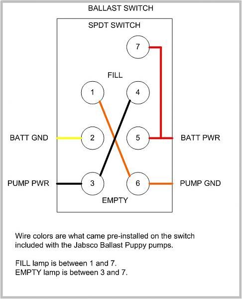
Which pumps did you purchase? The Jabsco pump come with a pre-wired switch, so all you need to do is connect it to the pump's black and orange wires and then connect the switch to a B+ and GND source. If you got the Johnson pumps, they do not come with a switch, so you will need to wire from scratch.Originally Posted by vandy654

Ballast Puppy switch3.jpg
Those 3 pumps will draw about 12-15 amps continuous. In order to draw from under the helm, you will need a B+ and GND BUSS bar that is feed with a sizable cable, like 4ga. If there's nothing under like that, then you will need bring a dedicated pair from the battery.
12Ga from the switch to the pump is sufficient.
Senior Member
I needed to make a minor edit here, just to clarify. Each pump can draw 12-15 amps continuous, but the initial spike can be close to 20A when the pump is first turned on. Once it gets spinning, the draw drops.
If you went with the Johnson pumps and will be wiring your own switch, here is a diagram.
Member
Thanks MLA - I have one Jabsco, and 2 Johnson pumps.
I am really interested in how the ballast would of been wired from the factory. I have an Outback, but the sticker in the boat actually says Outback/Mobius LSV. So the Mobius would of come with the factory ballast. If anyone has a 2002 Mobius or a similar year, can you please snap some pics how the wiring is done? Thanks for the help.
2002 Outback LSV
Member
ballast wiring2.jpgStill trying to figure out the wiring. I don't have a fuse box under the helm, so I am limited with options to get power to the switches. I removed the floor in the boat this weekend, I thought I would have a better option with trying to run the power from the batteries over to the helm, but it doesn't appear there is an easy way to do this. I can either try drilling holes in the fiberglass under the passenger seat and run wire between the gas tank and the ski locker, or run wire from the batteries around the front of the boat to the helm. Any suggestions would be appreciated!
ballast wiring2.jpg
2002 Outback LSV
Senior Member
With out a solid ground BUSS and B+/fuse block feed by some hefty cabling, you will need to pull a dedicated B+ and GND from the battery to the switches, with some circuit protection at the battery, like a breaker.
I would take the shortest route possible. No worries drilling a couple small holes to bass wire, as long as you know exactly where the bit is going to pop through to. Not into the fuel tank or stringer system. Depending on the length, you could do a single 8ga to the switches, or 3 12ga.....one for each switch.
Do you boat on Lake Jordan? Every time I cross that lake on 64, its wind whipped!
 Posting Permissions

 Reply With Quote
