


 Senior Member
Im getting ready to install the amps for tower speakers and subwoofer. I think i'm on the right track i"m just unsure of where to hook the power wire. The battery switch has 1 hooked to battery 1. 2 to the helm power and power wire from the engine. 1+2 is hooked to battery 2. I confirmed in the manual it is supposed to be this way. I'm confused. Any advise?

-2012 Supra Launch 21V
-2008 Mobius LSV
Senior Member
Get your power from the dist. block from battery 2, as well as the ground. Bat 1 and two should be grounded together, but I think it is common practice to run the distro + and - from batt 2
2006 Supra 20 - Sold
2006 Supra 24 Gravity Games - Sold
2015 Supra SE450 - Sold
Senior Member
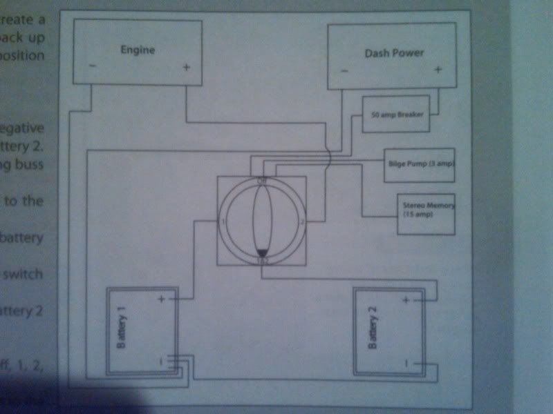
The "Where" wire needs to go to the "C" post of the switch. This keeps the entire audio system sharing the same power source.
The main B+ to engine and helm BUSS needs to be hooked to the "C" post also.
BATT-2 needs to be hooked to the "2" post.
The loads will draw from what ever battery you have the switch turned to.
Last edited by MLA; 04-20-2012 at 06:15 PM.
Senior Member
Brandon,
All grounds are common including the dual batteries, helm ground buss, engine block and all audio electronics grounds.
Perko, Blue Sea or other standard dual battery switch:
Switch terminal #1 goes to battery #1.
Switch terminal #2 goes to battery #2.
Switch common/output post connects to the alternator/starter feed, the helm supply buss via a breaker and all audio electronics via a master breaker/fuse and distribution. You can stack three terminal lugs on this single common/output post.
Nothing besides the dual battery switch connects directly to the battery(s) positives. The only exception would be a bilge pump/float switch if applicable and the HU memory as optional.
The above is the only acceptable way.
Note, if we are adding an ACR/VSR this scheme would change substantially.
Btw, you can get a comprehensive schematic from Odin.
David
Earmark Marine
Senior Member
Below is the diagram of how it is hooked up. I knew the power from the distribution block needed to go to the common lug. I guess I just don't understand why it comes wired this way from the factory and it makes me hesitant to change it. The boat has a pro mariner prosport12 battery charger, where should I have the switch when I am charging the batteries?
-2012 Supra Launch 21V
-2008 Mobius LSV
Senior Member
If your charger is a dual-bank, the switch should be off when charging. This isolates the 2 battery banks so the batteries can be conditioned independently.
Senior Member
Thanks got the batteries all charged up now.
Both amps require 4 gauge power wire, what gauge wire should I use from the distribution block to the battery?
-2012 Supra Launch 21V
-2008 Mobius LSV
Senior Member
You'll probably find that 1/0ga with a 120-150A fuse or breaker is sufficient, but knowing what specific amps you have and the apx distance between the battery and the amp wall would make calculating it easier, rather then a guess.Originally Posted by bzubke1

Senior Member
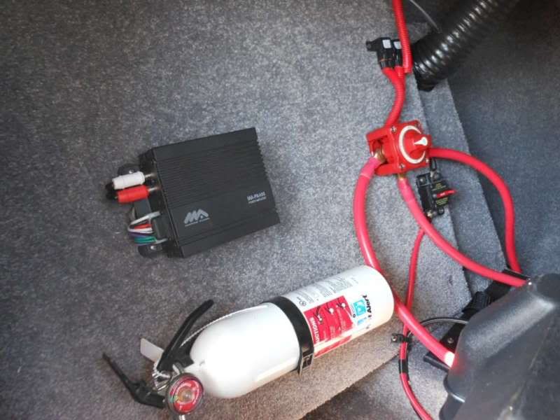
This is the amp rack in the boat, so I'm thinking less than 2ft of wire from the switch to the distribution block and less than 2ft of wire to each amp. The amps will be a wetsounds syn4(800watts) and alpine mrp-m500(500 watts). I have noticed most of the distribution black that have two 4ga outputs have a single 1/0ga input.
-2012 Supra Launch 21V
-2008 Mobius LSV
Senior Member
The total combined fusing for those two amps is 135A. With that length of cable run, I would do 1/0ga and a 120A Marine rated manual-reset breaker or fuse.
A 1 1/0ga in x 2 4ga out non-fused distrobution block is very common and will be exactly what you need. A couple of these and you are set. If you think you may, at some point down the road, add another amp, then I would consider a 3 or 4 4ga out block. This would give you that extra open slot for another amp.
If you want to get a little fancy, then look at the Tsunami FBWM802. Its a 1 1/0ga in x 2 4ga out ANL Fused block with volt meter. Use this in place of the breaker or single fuse since your amps are so close to the battery switch. For the GND side, use the DB8012 non-fused block.
 Posting Permissions

 Reply With Quote