


 Senior Member
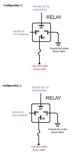
Quick question, I know it has been discussed before, but I wanted do double check. In the two drawings below, is there a correct or incorrect method? The only difference is pole 87 and 30, the remote out and +12v power in. I'm not hugely familiar with relay's, but I know I need to add one into the mix after the head-unit due to the number of components I am powering from the remote line.
Any input on preferred/correct method?
Super Moderator
What happened to the infamous paint drawings?
2016 Moomba Mojo
2006 Supra 24SSV - Traded
Senior Member
How do you think I made that one?
Super Moderator
Looked copied from somewhere ... nice use of text boxes.
Where are you looking at the relays? Radioshack, online, etc?
2016 Moomba Mojo
2006 Supra 24SSV - Traded
Senior Member
Any auto parts store has them, as well as radio shack
Senior Member
Configuration 2 is correct. In fact, in the link below, one of the wiring diagram examples is almost exactly the same scenario that you are using it for.
http://www.parts-express.com/resourc...ive-relays.cfm
Al
2006 Mobius LSV
Senior Member
Oh wait - the diagram in the link shows contact 85 & 86 to be reversed from what you show.
I have a wiring diagram from the relay I bought at home and can post up the instructions when I get home.
Al
2006 Mobius LSV
Senior Member
You have two isolated circuits there. One is the trigger or control circuit (86 and 85). The other is the workload circuit (30 and 87 at rest or 87a energized).
There really isn't a polarity for each independent circuit for all things to function the same. However, you could make the arguement to use the 30 terminal as incoming power since this is the hinged side and may serve to reduce any switching transients and noise.
David
Earmark Marine
Senior Member
Sooooooo........?
What?
Senior Member
Dusty,
Looking at my instructions, this how you need to wire it:
#85 to ground
#86 to switch (remote in from head unit in your case)
#30 to battery positive
#87 to device being turned on (your amps, EQ, etc)
Hope that helps.
Al
Al
2006 Mobius LSV
 Posting Permissions

 Reply With Quote