Senior Member
Alright guys, here is what I am working with so far. I'm looking to make sure I have this right. 2 main questions:
1. Do I have the tower speakers (Krypt) wired correctly to the Jl G1300 Amp? The Krypt are 4 ohm each, but I need it to be a 2ohm at the amp so each gets 150 watts. I originally thought that I needed to wire them in Parallel a the Roswell bar, and make on connection per pair to the Jl. However, looking at the JL, it has 2 + and 2 - inputs and says above them "min. 2ohm" So, if wired as my pic shows, straight from speaker to amp vs linking speakers, is the amp converting to a 2ohm output, or 150 to each speaker?
2. For the 4 channel amp, where will i be best served tying the last 2 Polk's in?
Also, any input regarding the rest of the layout is welcome. The Tsunami Distribution block is a fused block which holds 1 60 amp per each + output. It also is the ground distribution block, so it's all in one. I'm a bit unsure of how the dvc sub should be wired as well, but think I have it done the best and safest way.
Thanks in advance.
Last edited by dusty2221; 12-10-2010 at 02:05 PM.
Senior Member
Based on thisFrom the JL Manual, I believe I have it right, the amp parallels each pair itself at the input, converting to 2ohm. Which means I will be running 4 pair of 12g wire up the tower vs two pair and making a parallel connection at the speakers. Right?"You will notice that there are two “+” positive connections and two “–” negative connections. This is to facilitate multiple speaker wiring. The two positive and two negative connections are connected in parallel inside the amplifier. Connecting two speakers, each to one set of positive and negative terminals, will result in a parallel speaker connection. If only connecting one pair of speaker wires, it is not necessary to use both sets of connections."
Super Moderator
as far as in boat go, depending on the amp ... i would use 3 channels at wire them at a 2ohm load on the amp. When you get to the pair of speakers, wire them in parallel. This way you have all speakers hooked up to the amp and all pushing the same wattage.
2016 Moomba Mojo
2006 Supra 24SSV - Traded
Senior Member
Not having worked with any of the product involved, check the owners manual of the jl amps for the tower. if you are looking for a 2ohm load, you can run a pair of wires up to the roswell tower, then join them either series or parallel up inside the tower cans. that's what I did. I wired mine pos+pos and neg+neg to get a 3ohm load on my bullets, but did all the wiring inside the cans. much cleaner than 4 wires running up the tower. you should have wiring ran through the cans that you can pull out, again, using the string theory to feed the new wire. iirc, the holes in the cans are already big enough for a solid 12gauge wire to feed through it..
on the in-boat speakers, I ran my 4ch fosgate amp as follows: bow speakers ran to ch. 3-4 as a 4ohm load, one speaker to each channel. I ran the cabin speakers pos+pos and neg+neg, hooking up the 2 on the left side and the 2 on the rt side to ch. 1-2, presenting a 2ohm load to the amp.
'06 Supra Launch 20SSV-gone but never forgotten
Senior Member
Alright, So if I stick with the original plan, which was to make one run up the tower, (the 4 conductor 12g that KG linked to), then join inside the Roswell as shown, that creates a 2ohm...correct? What I drew is running 2 + and 2 -, then before the speaker, adding a connection to run to the other. Make sense?
And Kg, is this what you are referring to for cabins? Does 6 speakers running to the amp like this equal 2ohms per speaker?
Sorry for the silly paint drawings, but I am a visual learner, seeing it in text vs pic is night and day for me.
Senior Member
you are correct on the tower speakers. run the 4wire up the tower arm and once you are within the first can, split it off to the 4 speakers.
now on the 4ch kenwood amp, run ch. 3-4 with a single bow speaker on each channel.
run ch 1-2 with the 4 cabin speakers wired the same way as the tower speakers. that's what I would recommend. this will create a 4ohm load on 3-4 and 2ohm load on 1-2. you can use the gains to adjust the bow down just a little so they are more balanced.
'06 Supra Launch 20SSV-gone but never forgotten
Senior Member
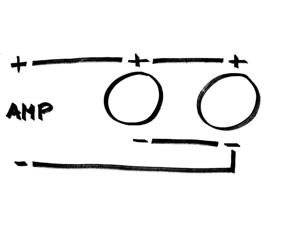
Dusty,Originally Posted by dusty2221

A better way to wire the speakers is to run the neg from the amp to the neg on speaker 1, the pos from the amp to the pos of speaker 2, then connect the negs of speakers 1 & 2 together, and the pos of speakers 1 & 2 together. This still presents a 2 ohm load to the amp, and you avoid all the splicing work making for a cleaner install and less signal loss. Below is a sketch (I'm not the Paint expert that you are)
This is also how you should wire your DVC sub. Just treat each voice coil like a separate speaker and wire it as shown in my little sketch.
This also applies to the in boat speakers where you are wiring two speakers per channel.
Also, below is a link that I found to be very informative and I think you will too.
http://www.termpro.com/articles/spkrz.html
Hope that helps.
Al
Last edited by cab13367; 12-11-2010 at 05:45 PM.
Al
2006 Mobius LSV
 Posting Permissions


 Reply With Quote